A while ago I got my hands on a pair of ESP32-Cam modules. They were crazy cheap and it looked like I had a great little device that would work well as a security or wildlife cam:

It’s tiny!

It was easy to program using the Arduino IDE and the example program, but no matter what I tried changing in the program it wouldn’t connect to my home wireless network.
There’s a lot of documentation out there on the ESP32 devices, but there are parts that seem to be missing. I wish I’d bookmarked the link, but I came across the comment section of one article that mentioned a 0R surface-mount resistor that selected the external antenna jack or the on-board PCB antenna. It didn’t take too long to find, and it was set to use the external antenna jack:

That explained why it wasn’t talking to the wireless – no signal. I could fix the problem in two ways: plug in an external antenna, or move the tiny little resistor so that it connected the ESP32 to the PCB antenna. I don’t have any connector that will fit that jack, so I decided to move the resistor.
**NOTE** Doing any combination or number of the following steps will definitely, POSITIVELY void the warranty of the device. It may also increase the electrical noise produced by the unit and/or its susceptibility to other sources of electrical noise. It may also cause operational or stability problems. It may also cause the device to produce wifi signals that are more powerful than allowed by law. Proceed at your own risk.
Unfortunately, between not being able to see it very well (even with a magnifier lamp), having a soldering iron with too large a tip, and having tingly fingers and shaking hands, I ended up with this:

Not only did I not manage to solder the resistor in place, I also ruined the PCB pad that connected back to the ESP32.
By this point I was getting pretty frustrated. Actually, I don’t think I’ve been that frustrated in quite a while. Fortunately, I had another ESP32-Cam that I could apply the knowledge that I gained on this one and not make the same mistake twi-bahahahaha… yeah, I ruined that one, too.
The two of them together cost me less than $15, but I hate throwing something out when it’s still “alive” (they both still booted and tried to connect to the wifi), and I was looking forward to playing around with them. Seeing as how they were pretty much garbage at this point anyway, I figured I’d see if there was anything I could do to get them working.
**NOTE** See previous note. Seriously.
I could see the PCB trace leading under the metal can, so I figured that if I was careful, I might be able to remove the can and find another soldering point to attach an antenna.
To remove the can, you don’t need a hacksaw or a Dremel… just a pair of very fine-tipped pliers or snippers. there is a small hole in the can in the inside corner right by where the antenna selection resistor pads are. Carefully grab it with the pliers/snips and pull straight upwards to make some room:

Slide the pliers in a bit more and lift up and away from the PCB antenna (towards the top of this picture). It may take a bit but the can end by the PCB antenna should break away:

Reposition and pull the can up and to the left – the right side and top should come free easily as well:

Reposition again and the last bit should break away with very little force:

The antenna connection point is – very nicely – right by where the antenna selection pads are, right between two surface-mount components with big pads and lots of solder:

So now to make the antenna. I used a piece of 26ga solid wire-wrap wire, but anything nice and thin will do 22ga is too big.
Cut a piece about 6.5cm long, then strip about 1-1.5mm and bend the stripped part at a right angle. Tin the wire, make sure it’s got a good coat of solder on it:

Bend the insulated part of the wire to whatever shape and angle helps you hold the stripped part in place at the new attachment point. Use the iron sparingly – if you’re heating and heating and it doesn’t seem to be melting, back off, give it a minute, and change your angle before trying again.
If you’re careful and lucky, you’ll end up with something like (or much better than) this:
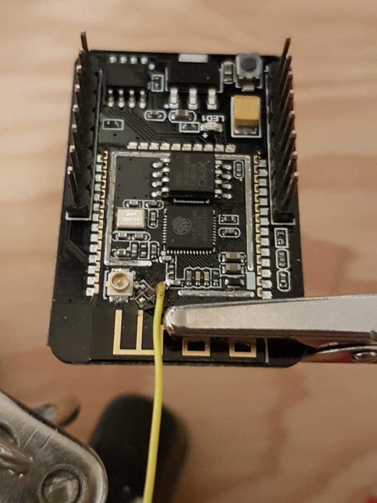
Gently bend the antenna into the orientation you prefer, and you’re done!

The next thing to try is powering it up (unless you haven’t programmed it, in which case you should probably do that now). With no can and a crappy detuned wire antenna, the ESP32-Cam was able to finally connect to my home wireless network:


And the camera’s video streaming works like a charm:
I suppose that instead of hanging a wire antenna off that point, I could’ve run a jumper from the new attachment point to the pad that connected to the PCB antenna (or the antenna jack, for that matter), but a) I just thought of it, and b) I don’t mind the crappy antenna look.
Thanks Mark, you saved me from trashing my ESP32-CAM, after I trashed the same solder pad when trying to change from the internal antenna to an external one.
Hi Paul! I’m glad it helped – that solder pad is way too easy to mangle.
Thanks for the comment!
Funny! I just had the same experience…
* Unable to see in which position the resistor was placed.
* Too big of a soldering iron
* Pads disappeared..
etc.etc.
I hear you… the pads are so small and can’t take much heat at all!
Were you able to get it working?
OMG. Its a 0 (zero) Ohm resistor. Just drop a blob of solder across the two pads and you’re done. You don’t even need to remove the old resistor to the external antenna and you’ll still get great reception.
Hey DaHai!
That certainly seems like an easier way to do it – I didn’t know it was a zero ohm resistor. Thanks for the info, much appreciated!
@DaHai
OMG. That is exactly what I did and now the wireless does not work due to the solder blob not going to the right place.
But thanks to this blog I have a chance to fix it.
Hi, thanks for sharing this, will try it! Btw did you measure the exact signal strength? Also did you try it with different cable types and lengths? Could be useful to know what works the best.
Hi Laszlo! Thanks for the comment!
I was going for a simple half-wave whip, which worked out to about 60mm, with a little extra for soldering. I don’t know if quarter-wave would perform better, but it’s half the length and I was wondering if enough wire would get far enough away from the ground plane in the board to work well.
I haven’t tested the signal strength beyond getting it connected to my home network, but I have a couple of other antennas I want to test with the ESP32. When I do that I’ll be sure to test the little wire antenna too.
Have a good day!
Excellent job, thank you for sharing! I dropped my ESP32-CAM and it stopped connecting, I found your post and managed to connect those two little pins together with some very small wire – it works thanks to you! 🙂
Hi Matt!
Glad to hear it – thanks for the comment!
Hello Mark,
Thank you very much for your detailed and competent presentation. You have brightened my day and I save 10€.
Kind regards, Axel
Hi Axel – thanks for the comment!
I’m happy to hear that you were able to save your ESP, they’re great little devices!
Hi! I just followed your directions here after mangling my own antenna pads and… it works! Thanks for this writeup! I was worried I’d have to track down the pinout of the daughter-board myself– didn’t even think of making my own antenna.
That’s great! I’m glad to hear you got things working again. I find those pads pretty tricky to deal with.
Have a good day!
Thanks a lot for the workaround. I had ruined my ESP32 trying to change the SMD resistor and was about to throw it away.
Your workaround worked perfectly. Soldered just a piece of wire. Perfect!!
Hello Reinhard!
Thanks for the comment – I’m glad to hear that you were able to save your ESP32!
Thanks a thousand, with your super tutorial I was able to bring my esp32 back to life. works perfectly! Greetings Johannes
Hi Johannes!
That’s great – I’m glad to hear you were able to keep using your ESP32!
Thanks for the comment!
Thanks for this article.
I’d gladly pay 1$ more for this board to allow switching antennas with a simple jumper instead of using this mechanism so hard to solder back.